Select the device which you develop the application for:
Today we are going to learn:
- What is a composite character;
- What does „parent sprite“ and „child sprite“ mean;
- How to build a coposit character using different parts;
- How to move sprites upwards or down using the Z= command.
- Make simple animations of a composite character.
In Game Pilot, a character may consist of several images. This type of character is called composite character. In the description of a character, the connections between these images should be described.
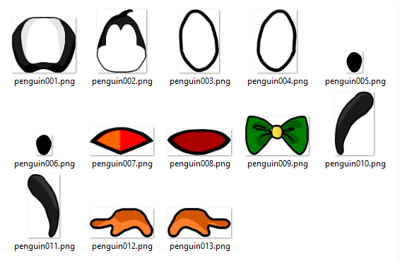
On the image below, we see different parts of a penguin:
Each part is a standalone image and belongs to the penguin character. In Game Pilot, you can make so that all these parts are connected to each other and that they move using a certain algorithm.
First, we will put all these parts so that we get a penguin. To begin working on it, we need a .sc-file, a background and a set of images for the penguin character.
Start Game Pilot, select "Prepare demo project", then select the "9 Composite characters" project. Open the project.
The Lesson009.sc file:
- - - - - CODE BEGIN - - - - -

// Lesson 9. Composite character

Scene Start

Png(Background,,,1024,768)

- - - - - CODE END - - - - -
Note that we don't have a penguin on the scene yet. But we will build it using the parts you have seen on the picture above. First, we have to make sure that the parts of the penguin are numbered conveniently. We will choose a part to which other parts will be attached, and use the number 001 in its name: penguin001.png. The remaining parts will be numbered according to the same principle: a part to which other part(s) is/are attached is numbered first.
The main part of the penguin is the body.
The head will be attached to the body.
To the head will be the following parts attached: the bow, the beak and the eyes (the whites).
Pupils attached will be attached to the whites.
And the wings and the legs will be attached to the body as well.
Whatever movements the body makes, the head, the wings and the legs will always follow it. And whatever movements the head makes, the eyes will follow it. And so on. So one can say that the body is a „parent“ of the head, wings and legs. And the head is a „parent“ of the eyes and beak. An image of a composite character, to which another image of this character is attached, is called parent sprite. And the image that is attached to the parent image is called child sprite. One image can be a child sprite for another image, but simultaneously a parent sprite for the third one. One image can have several child sprites.
Since the main part of the penguin is the body, we will give it the name penguin001.png.
Then we will give names to all the images that should be attached to the body.
Head - penguin002.png
Eyes (whites) - penguin003.png and penguin004.png
Eyes (pupils) - penguin005.png and penguin006.png
Beak - penguin007.png
The bottom part of the beak - penguin008.png - will be attached to the top part.
Bow - penguin009.png
The following sprite will be attached to the body:
Wings - penguin010.png and penguin011.png
Legs - penguin012.png and penguin013.png
Now that we are sure the sprites are numbered conveniently, we can add the penguin character to the scene:
- - - - - CODE BEGIN - - - - -

// Lesson 9. Composite character

Scene Start

Png(Background,,,1024,768)

Person(penguin,1, 100,100)  // Penguin

- - - - - CODE END - - - - -
Now we can create the penguin.stt file. For now it will look like this:
- - - - - CODE BEGIN - - - - -

Scale = 50

Parent[1]=0

Rest

1: Delay=0 Img[1]=1

   Rest

- - - - - CODE END - - - - -
The numbers 1 and 0 in the Parent[1]=0 string indicate the numbers of the character sprites. You can read this string as follows:
The parent of the sprite 1 is sprite 0. Such a record is necessary for each sprite, besides the sprite 0. Sprite 0 is the character itself.
The command Parent[1]=0 means: create sprite 1, the parent of which is sprite 0.
Such an entry in the header of the .stt file must be done for each sprite, except for the sprite 0. Sprite 0 is the character itself. When a character is created, sprite 0 is created automatically, so you can immediately assign an image to it with the Img [0]=N command. Other sprites must be created with the Parent command and it is important to create them in a specific order - if you do not create sprite 1, the Parent [2] command will not be executed.
Next in the character code is:
Delay=0 Img[1]=1
Img[1]=1 means: to the sprite [1], the image 1 is corresponding.
Also, create the file penguin.stt with the content described above.
Transfer the file penguin.stt and the edited file Lesson009.sc to your iPad using FTP or using USB.
Run the project in Game Pilot.
Note that the body is in the corner of the screen. Open the editor. As you open the window, Game Pilot automatically goes to the Wait mode. In this mode, drag the body so that it is in the middle of the screen. The coordinates of the body have changed in the .sc-file. Save the file and run the project (Run).
The next changes, we will make in the penguin.stt file. You can make it either on your iPad or on the computer. If you make some changes on the iPad and some changes on the computer, please make sure the files you have changed on the iPad are updated on the computer as well.
Now we will attach the head to the body. When we add a new sprite to a scene, we need to determine its parent first. The parent of the head is the body. The head is sprite 2. The body is sprite 1. Therefore, the parent of sprite 2 is sprite 1. We can record it as follows: Parent[2]=1.
- - - - - CODE BEGIN - - - - -

Scale = 50

Parent[1]=0 Parent[2]=1

Rest

1: Delay=0 Img[1]=1

   Rest

- - - - - CODE END - - - - -
But if we start the project with these changes, we won't see the head. We have a command Img[1]=1 that puts the body on the screen. But we don't have a command that puts the head on the screen.
The head (sprite 2) corresponds to the image penguin002.png (i.e. image 2). Therefore we will record: Img[2]=2. This means: to the sprite 2, the image 2 is corresponding.
We could assign a different image to the sprite 2. For example, the image 9. Then we would write: Img[2]=9
Task 2:
Add the records Parent[2]=1 and Img[2]=2 to the file penguin.stt:
- - - - - CODE BEGIN - - - - -

Scale = 50

Parent[1]=0 Parent[2]=1

Rest

1: Delay=0 Img[1]=1 Img[2]=2

   Rest

- - - - - CODE END - - - - -
Run the changed project.
We see that the head does not appear in the appropriate place. This is because we didn't set its coordinates.
Since the body is a parent for the head, we can also say that the head is a child sprite towards the body.
If we don't set coordinates for a child sprite, it will be attached to the parent sprite as follows:
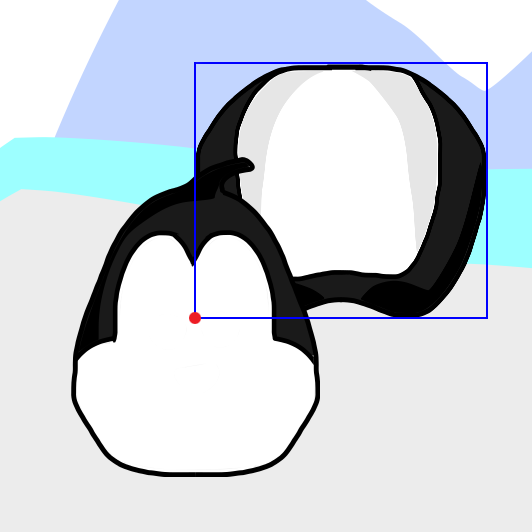
The center of the child sprite (head) is attached to the bottom left corner of the parent sprite (body).
Run the Penguin project again. Look that the middle of the head is in the bottom left corner of the body image:
If we make the head rotate (using the dA command), it will rotate relative to its own center (which is marked with the red spot).
We need to attach the head to another point of the body.
We can also set another point on the head, in which the head will be attached to the body. For example, we can set a point in the middle but in the bottom part of the head.
If we then make the head rotate, it won't rotate relative to its own center anymore, but relative the point in the bottom part of the head.
If we attach the head to the body in this point, we will get:
For this purpose, we will need the following commands:
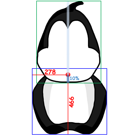
Img[2]=2 X[2]=278 Y[2]=466 OX[2]=50 OY[2]=10
You know already the command Img[2]=2. It means that for the sprite 2, we will use the image 2 (penguin002.png).
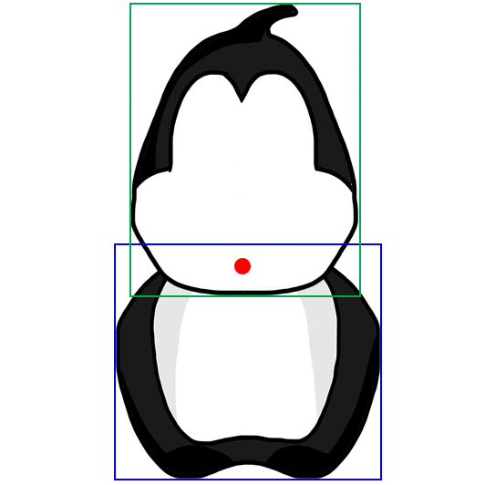
The coordinates X[2]=278 Y[2]=466 — are coordinates of the point on the parent (on the body), to which the child sprite (the head) will be attached. On the picture below, this point is marked with a red spot:
These coordinates are defined relative to the bottom left corner of the parent image. Note that when Game Pilot determines coordinates of a composite character, it ignores the command Scale=50, which may be in the head of the file. Game Pilot calculates coordinates of child sprites based on the actual size of the images. So you can define these coordinates in an image editor.
OX[2]=50 OY[2]=10 — this is location of a rotation point of a child sprite (head). O means rotation center. These two values are expressed in % of the size of a child sprite. When you look how the head is attached to the body, you will see that the rotation point is in the middle of the head, so X=50%, and OX[2]=50. But in Y this value is only 10% from the height of the head. Therefore, OY[2]=10.
If the rotation center of a child sprite is not defined, it will be in the middle of an image by default.
Now, we will add the property Z[2]=1 to the commands described above:
The Z property indicates if a child sprite is above or under the parent sprite. When Z is 1 or other positive number, the child sprite is above the parent sprite. If Z is a negative number (for example, Z[2]=-1), the child sprite is beneath the parent sprite.
Task 3:
To the code of peiguin.stt file, add a string that describes how the head is attached to the body. It will look like this:
Now use a negative value for the Z property. (Z[2]=-1 instead of Z[2]=1). What has changed? Change it back so the head is over the body.
Now we will add a next sprite – the right eye white. This is image penguin003.png. The right eye is actually in the left on the penguin's face, because the penguin is turned to us. The eye will be attached to the head. Therefore, the head (sprite 2) is the parent of the eye (sprite 3).
So in the head of penguin.stt, we will write: Parent[3]=2
And in the state 1, the 3rd string will look like this:
Img[3]=3 Z[3]=1 X[2]=… Y[2]=… OX[2]=50 OY[2]=50
Img[3]=3 means, that for sprite 3, we will use image 3.
Z[3]=1 means, that the eye is above the head.
OX[2]=50 OY[2]=50 - these two commands mean that the rotation center of the eye (and simultaneously the point in which the eye will be attached to the head) will be exactly in the middle of the eye image.
Now we only need to define the location on the head, to which the eye will be attached, and insert the values here: X[2]=… Y[2]=…
Task 4:
Open the image of the head in any image editor that allows you to define coordinates for a point on an image. Find the point where the middle of the right eye should be attached, define its coordinates and insert the appropriate numbers: X[2]=… Y[2]=…
Make the appropriate changes in the file penguin.stt. Run the project and look if the eye is where it should be. If it is in a wrong place, try to fix it.
Task 5:
In the same way, add the remaining parts of the penguin.
You may get the following problem: the wings are over the head. To put the wings over the body but beneath the head (head is the sprite 2), write for the head: Z[2]=2. And for the wings (sprite 10 and sprite 11) write: Z[10]=1 and Z[11]=1.
The head and the wings have the same parent – the body. The sprites are put on the screen in order of increasing of the Z value. Therefore, sprites with smaller Z value are put under the sprites with higher Z value.
So we will get for the head:
Img[2]=2 Z[2]=2 X[2]=278 Y[2]=466 OX[2]=50 OY[2]=10 // head
It is practical to write comments after each string so we know for which part of the character we use a certain sprite.
Below is the approximate code which you should get when you build up the penguin:
Now that we have build up the penguin, we will try to get it move.
First, we will make the penguin breathe. That means, its body will increase and decrease.
At the end of the state 1 (above the string with the Rest command), we will add the following string: State=2
Now, we will create the state 2:
// Breath

2: Delay=700 dS[1]=1 // breathe in

   Delay=700 dS[1]=-1 // breathe out

   Delay=0 State=2
dS[1]=1 means „smoothly increase the image at 1%.
dS[1]=-1 means „smoothly decrease the image at 1%.
At the end of the state, there is a command State=2, i.e. we go to the beginning of the state. So we've got a cycle.
Task 6:
Make the changes described above and run the project.
Note that it is not only the body that increases, but also the other parts of the penguin. But we need that only the body increases.
Whatever a parent sprite does, child sprites follow it. And if a parent sprite increases, child sprites will increase, too.
We can tell the child sprites to decrease at 1% whereas the parent sprite increases at 1%. And to increase at 1% whereas the parent sprite decreases at 1%.
The sprite 1 has the following child sprites: 2, 10, 11, 12, 13. The other sprites (3, 4, 5, 6, 7, 8, 9) are child sprites of the mentioned sprites. If we care about the right size of the sprites 2, 10, 11, 12, 13, the sprites 3, 4, 5, 6, 7, 8, 9 will have right size as well.
Make the changes described above and run the project.
Look at the penguin. Do the other parts of the penguin change their size now?
But note that the legs of the penguin are moving down and up. This is because they are attached to the body. The body increases and the points where the legs are attached go down. Although the legs retain their size, they move, that actually shouldn't happen.
To prevent the legs moving up and down, we can use the command dY:
dY means move up (if the number is positive) or, move down (if the number is negative).
dY[12]=... means move sprite 12 (the right leg) at a certain number of points up or down
dY[13]=... - move sprite 13 (the left leg) at a certain number of points up or down
Now, we need to insert an appropriate number. We will try the number 3 first. In the next line, we will take „-3“, a negative number, because the leg should be moved back down.
Task 8:
Make all the suggested changes and run the project. Are the legs now moving up and down on the screen? When the legs are still moving, try other numbers.
Now, let us add another movement. For example, the penguin wings. We will create a new state for this purpose.
Since we add movement states one after another, it is better when we first create a state where we open all other states.
When the state 1 ends, we go to the state 2 because at the end of the state 1 is the command State=2.
We can change the state 2 so it opens all other new states with the New command. And the state that previously had number 2, can be renamed into state 3. Result:
// Initialate movements
2: New=3 // execute new state 3
Rest
Note that there is a command State=3 at the end of the state 3. As it was state 2, the command was: State=2
Task 10:
Make the changes described above. Also, add the state 4, which describes how the penguin wings. Use the Angle property for these movement. This property was described in the Lesson 4.
Now, add movements of pupils and blinking. Create a new state (state 5) for the eye movements. Think about how the penguin should move the pupils. Think about what command you have to use to make him blinking.
Task 12:
Try to make the following: when you touch the head of the penguin, the head is shaking.
Below is the approximate code of the penguin.stt file:
// Head shaking
6: if TouchIndex<>2 Rest
Delay=0 if HeadTouch=1 Rest // when the head is touched and it is shaking, ignore the next touches
Delay=0 HeadTouch=1
Delay=800 Angle[2]=-10
Delay=800 Angle[2]=10
Delay=800 Angle[2]=-10
Delay=800 Angle[2]=0
Delay=0 HeadTouch=0 // the head isn't shaking anymore, now you can touch the head again
Rest
- - - - - CODE END - - - - -
We should also add the following string to the Lesson009.sc file:
HeadTouch=0 // Penguin does not shake his head
The HeadTouch variable indicates if the penguin is shaking its head or not. If the penguin is shaking its head, the variable value is 1. If you touch the head once again as the penguin is shaking it, the penguin won't be shaking the head two times simultaneously (see state 6).
The command Slot[Touch_Self]=6 was added to the head of penguin.stt. State 6 was added as well. The first string of the state is: if TouchIndex<>2 Rest
The TouchIndex value indicates which child sprite was touched.
If we touch the right leg, the TouchIndex value will be 12.
If we touch the bow, then TouchIndex value will be 9.
And if we touch the head, then TouchIndex will be equal to 2.
The string if TouchIndex<>2 Rest means, if TouchIndex is not equal 2 (i.e. we touched any part of the penguin but not the head), the penguin goes to Rest and the commands below are not executed.
If TouchIndex=2 (i.e. we touched the head), the commands below are executed.
Perhaps you noticed that touching the head does not work always. We have this string in the State 6;
if TouchIndex<>2 Rest
If you touch the beak, then TouchIndex = 7, so the penguin will not shake its head. If you want the touching of the beak to be treated as if the head were touched, then you can fix it like this:
if (TouchIndex<2) Or (TouchIndex>9) Rest
There is also another solution - when initializing (at the end of the header or at the end of the 1 state), you can specify that the sprites 3, 4, 5, 6, 7 and 8 do not respond to the touch:
Note that if you want to make a long animation of the penguin but without using a composite character, you will need thousands of pictures. It will take up a lot of space on the computer and a lot of time to draw all these pictures. It is much easier to create such animations using composite character pictures.